
Properly sizing a control panel and float switch for a lift station ensures reliable wastewater management and prevents system failures. This comprehensive guide walks you through calculating electrical load requirements, selecting appropriate NEMA enclosures, and configuring level control switches for automatic pump operation. Expect to complete this process in 3-4 hours with intermediate electrical knowledge.
Before You Begin: Prerequisites and Safety
Contents
- 1 Before You Begin: Prerequisites and Safety
- 2 Step 1: Calculate Electrical Load Requirements for Pump Motors
- 3 Step 2: Determine Control Panel Specifications and NEMA Enclosure Size
- 4 Step 3: Select Float Switch Types and Quantity for Water Level Monitoring
- 5 Step 4: Establish Float Switch Spacing and Wet Well Placement
- 6 Step 5: Wire Control Panel Components and Install Float Switches
- 7 Step 6: Test Pump Station Automation and Verify Operation
- 8 Troubleshooting Common Control Panel and Float Switch Issues
- 9 Next Steps: Maintenance and Monitoring
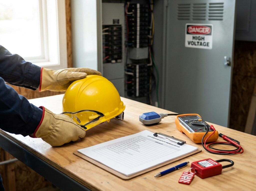
Required Tools:
- Multimeter for voltage and amperage measurements
- Wire strippers and crimping tools
- Screwdrivers and drill with appropriate bits
- Tape measure for float switch spacing requirements
- Pump curve and specification sheets
Required Materials:
- Pump specification data including horsepower and voltage requirements
- National Electrical Code (NEC) reference manual
- Wet well dimensions and basin volume calculation data
- Inflow rate determination records
Safety Requirements:
- Shut off electrical service before working on control circuit design
- Use lockout/tagout procedures on circuit breaker
- Verify proper grounding for all electrical enclosures
- Wear appropriate PPE including electrical-rated gloves
Step 1: Calculate Electrical Load Requirements for Pump Motors
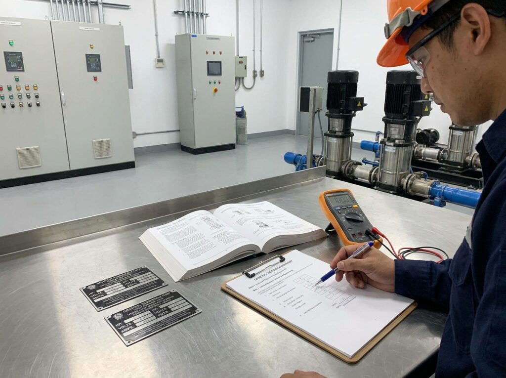
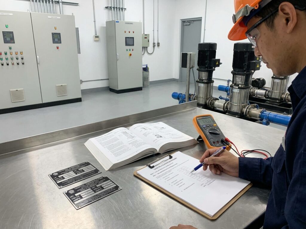
Begin by determining the motor current rating for your sewage pump or submersible pump. According to the National Electrical Code (2023), motor protection devices must account for starting current, which typically reaches 6-8 times the running amperage during across the line starter activation.
Calculate Total Amperage for Pump Station
For a simplex pump system, multiply the pump’s full load amperage (FLA) by 1.25 per NEC Article 430.32. A duplex pump system requires calculating combined load when both pumps operate simultaneously. For example, two 5 HP three phase pumps at 208V draw approximately 17 amps each (based on typical pump power consumption). Total load equals 17A × 2 pumps × 1.25 = 42.5 amps minimum.
Account for Additional Control Components
Add electrical load requirements for auxiliary equipment:
- VFD (variable frequency drive) adds 5-10% to motor current rating
- Control transformer typically draws 1-3 amps
- Alarm system components consume 0.5-2 amps
- High level alarm indicators add minimal load (0.1-0.5 amps)
A triplex pump system for municipal lift station applications requires more complex pump sequencing logic and higher electrical service sizing.
Step 2: Determine Control Panel Specifications and NEMA Enclosure Size
Select an electrical enclosure based on calculated amperage and environmental conditions. According to UL 508A standards (2021), lift station control panel sizing must accommodate all components with 20% spare capacity for heat dissipation.
NEMA Enclosure Selection Criteria
| NEMA Rating | Application | Minimum Dimensions |
|---|---|---|
| NEMA 1 | Indoor pump room layout only | 24″ × 20″ × 8″ for simplex |
| NEMA 4 | Outdoor wastewater pump station | 30″ × 24″ × 10″ for duplex |
| NEMA 4X | Coastal lift station (corrosion resistant) | 36″ × 30″ × 12″ for triplex |
Component Spacing and Ventilation Requirements
Ensure adequate control panel layout with these specifications from UL standards (2023):
- Minimum 6-inch clearance between motor starter and panel walls
- Terminal block sizing must accommodate wire gauge determination (typically 10-14 AWG)
- Panel door interlock required for voltages exceeding 50V
- Ventilation openings totaling 10% of panel surface area for heat management
Step 3: Select Float Switch Types and Quantity for Water Level Monitoring
Choose appropriate level sensor technology based on sewage handling requirements. According to the Hydraulic Institute standards (2022), piggyback float switches work best for residential sewage lift stations, while vertical float switches suit commercial applications.
Float Switch Selection Guide for Wastewater Applications
Tether float switches provide reliable fluid level detection in wet wells with diameter greater than 24 inches. Vertical float switch designs offer precise pump activation levels in confined spaces. For grinder pump station or effluent pump station installations, avoid mercury switch technology due to environmental concerns.
Alternative technologies include:
- Pressure switch for effluent pump system applications (±0.5 PSI accuracy)
- Ultrasonic sensor for non-contact liquid level switch placement (±1% reading accuracy)
- Capacitance probe for sewage ejector system with high solids content
- Pneumatic switch for explosion-proof sump pump control environments
- Transducer systems for remote monitoring control panel integration
Determine Float Switch Quantity Based on System Type
For a simplex pump system, install minimum 3 float switches: pump start switch (ON), pump stop switch (OFF), and high water alarm switch. A duplex pump system requires 5 switches for proper pump alternation control: lag pump activation, lead pump selection, common stop, high level alarm, and emergency overflow prevention. According to industry best practices (National Association of Wastewater Technicians, 2023), triplex sewage pump station configurations need 7-8 float switches for complete pump control logic.
Step 4: Establish Float Switch Spacing and Wet Well Placement
Calculate float spacing requirements using this formula: Minimum spacing (inches) = (Pump flow rate GPM ÷ Basin area sq ft) × 0.5. For a duplex sewage pump station with 100 GPM pumps in a 6-foot diameter wet well (28 sq ft), minimum spacing equals (100 ÷ 28) × 0.5 = 1.8 inches between switches.
Float Switch Installation Height in Lift Station Basin
Set float switch setpoints for automatic pump station operation using these guidelines from the Hydraulic Institute (2022):
- Pump stop level: 6-12 inches above pump suction inlet to prevent air entrainment
- Lead pump start: 18-24 inches above stop level (allows 2-4 minute pump cycling frequency)
- Lag pump start: 12-18 inches above lead pump start for pump alternation
- High alarm: 12 inches below wet well overflow elevation
- Emergency high: 6 inches below overflow (triggers backup power integration)
According to pump manufacturers (2024), proper float switch differential settings prevent excessive pump cycle control that reduces motor efficiency rating and increases maintenance accessibility needs.
Step 5: Wire Control Panel Components and Install Float Switches
Follow this pump control wiring procedure for UL listed installations:
Control Panel Wiring Sequence
- Install circuit breaker sized at 250% of motor full load amperage per NEC 430.52
- Mount magnetic starter or combination starter with proper thermal overload protection
- Connect contactor coil to control voltage selection (typically 120V from step down transformer)
- Wire overload relay contacts in series with contactor coil for motor protection device functionality
- Install HOA switch (Hand-Off-Auto) for manual pump override capability
- Add alternator circuit for lead pump selection in duplex configurations
Float Switch Cable Entry and Termination
Route float switch cables through conduit specifications that meet NEC 314.16 box fill calculations. Use liquid-tight flexible conduit for cable entry provisions into NEMA 4 enclosures. Terminate float switch wiring on clearly labeled terminal blocks with wire sizing requirements of 14 AWG minimum for control circuits. Perform voltage drop calculation to ensure control voltage remains above 90% rated value per NEC 210.19(A).
Step 6: Test Pump Station Automation and Verify Operation
Energize the electrical panel with main disconnect switch and verify control transformer output voltage. Test each pump control switch individually by manually raising floats to simulate water level monitoring conditions. Confirm proper pump sequencing logic in duplex pump system by observing alternation between pumps on successive cycles.
Verify Safety Interlocks and Alarm Notification System
Test high level alarm activation and confirm audible/visual alarm notification system functionality. Verify emergency overflow prevention by simulating high water conditions. Check that overload protection circuits trip appropriately by gradually increasing load on test pump. According to OSHA 1910.147 standards (2023), document all inspection requirements and duty cycle considerations for compliance records.
Troubleshooting Common Control Panel and Float Switch Issues
If pump fails to start when float reaches ON position: Check contactor coil voltage (should read 110-120V AC), verify float switch continuity with multimeter, and inspect overload relay reset status.
If both pumps run simultaneously in duplex system: Verify alternator relay operation, check pump control diagram matches actual wiring, and confirm lag pump activation float switch operates at correct level.
If pump short cycles (runs less than 1 minute): Increase float switch differential settings by raising stop level or lowering start level. Calculate if pump capacity matching exceeds inflow rate determination by more than 4:1 ratio, indicating oversized pump selection.
If control panel trips breaker frequently: Verify electrical service sizing meets calculated load plus 25% safety factor. Check for voltage drop exceeding 3% using power monitor equipment. Inspect motor windings for ground faults using megohmmeter set to 500V DC.
Next Steps: Maintenance and Monitoring
Schedule quarterly inspection requirements for pump station design integrity. Implement remote monitoring control panel systems for real-time alarm notification system updates. Consider adding generator compatibility testing to backup power integration protocols. Review surge protection requirements annually and verify proper power factor correction equipment operation. Consult local wastewater management authorities regarding compliance with stormwater pump station regulations and sanitary sewer pump discharge permits.